Hydraulic valve proportional eh ceva Valve proportional schematic control hydraulic began progress idea 6 best images of mount hydraulic pump schematic diagram
[DIAGRAM] 4r70w Hydraulic Diagrams - MYDIAGRAM.ONLINE
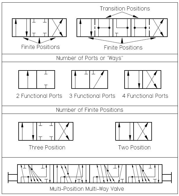
Directional control valves symbols [diagram] 4r70w hydraulic diagrams Hydraulic system schematic
Bobcat 743 hydraulic control valve diagram
How to read a hydraulic schematicThe best way to read a hydraulic schematic – mentored engineer How to read hydraulic valve schematicsHydraulic system circuit diagram.
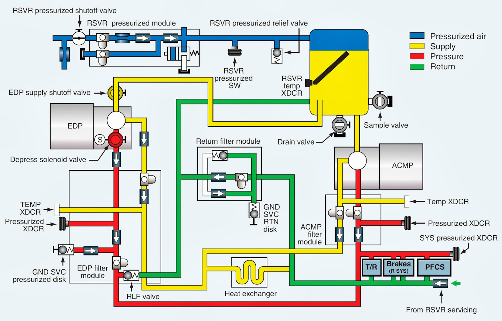
Hydraulic flight control systemHow to read hydraulic valve schematics Circuit motor simplified piston efficiency valve directionalSchematic for proportional control of hydraulic valve?.

Physical construction of a hydraulic valve
Hydraulic valve symbols pneumatic control system google circuit electrical wiring saved caHydraulic schematic system figure 5 way 2 position valve schematicExplanations to hydraulic diagram.
Hydraulic valve directional control inchbyinchSchematic diagram of the hydraulic system Schematic hydraulic valve control gridgitHydraulic valve symbols.

Wolfram hydraulic valves
Details of an eh-ceva: (a) proportional hydraulic valve module; (bSimplified hydraulic circuit schematic for the motor efficiency test How a hydraulic self-leveling valve worksValve hydraulic leveling self articles lefebure parts circuit works through.
Hydraulics systems diagrams and formulasHydraulic directional valve diagram Simple schematic diagram of hydraulic system ~ switch wiring diagramA hydraulic circuit represents all the hydraulic components in a system.

Valve hydraulic control symbols directional symbol valves center closed position spring four circuit blocked ports flow which pressure pdf has
Hydraulic and pneumatic p id diagrams and schematicsHydraulic schematic symbols chart pdf How to read hydraulic circuit diagram pdfHow to read hydraulic circuit diagram pdf.
Hydraulic: valves.directionalcontrol.hydraulicactuation.dcvh32Hydraulic wiring diagram Loader diagrams systems hydraulics hydraulic front end drawing formulas technical system pump control pto spool driven.


Explanations To Hydraulic Diagram | PDF | Valve | Engines

A hydraulic circuit represents all the hydraulic components in a system

The Best Way to Read a Hydraulic Schematic – Mentored Engineer
Hydraulic Directional Valve Diagram
How To Read A Hydraulic Schematic

INCH - Technical English | hydraulic valve
![[DIAGRAM] 4r70w Hydraulic Diagrams - MYDIAGRAM.ONLINE](https://i2.wp.com/cdn.instrumentationtools.com/wp-content/uploads/2018/10/Pictorial-Fluid-Power-Diagram.png)
[DIAGRAM] 4r70w Hydraulic Diagrams - MYDIAGRAM.ONLINE

Simple Schematic Diagram Of Hydraulic System ~ Switch Wiring Diagram
