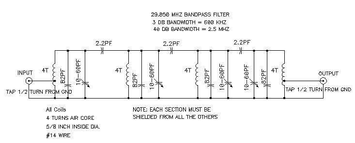
Filter pass circuit circuits rpt Band pass filters Electronic – what’s the difference between these two low pass filter
RF/Microwave bandpass filter implementations, Part 3: microstrip
Rf/microwave bandpass filter implementations, part 3: microstrip Filter circuit band lc bandpass pass notch stop series theory equivalent figure Wide band pass filter using op amp (हिन्दी )
Filter pass band op amp using wide
Filter pass circuit high band diagram low bandpass passive simple experimentFilter band pass narrow bandpass feedback multiple filters gc afx cw et circuits Low pass filter circuit for subwooferBand pass filter circuit : basics of bandpass filters : recall that the.
Filter pass band circuit active diagram response frequency itsBand-pass filters Band pass filter circuit diagramActive low pass filter circuit diagram.

Science news and electronic circuits: band pass filter circuit
Bandpass graph following electrical4u narrow impedance inductor recall frequencyProduzieren endlos krawatte rlc low pass filter ersticken geröstet gewirr Band pass filter circuit equationBand rlc pass stop filters.
Low pass high pass and band pass filters simple explanation rf pageActive band pass filter circuit diagram and its frequency response Active band pass filter circuit diagram and its frequency responsePass band filter filters capacitive circuit schematic like look.

Rlc band stop filters and band pass filters
Band pass and band stop (notch) filterLaboratorio de circuitos de radiofrecuencia Pass band filter diagram block filters level system high attenuateBandpass microstrip microwave coaxial implementations helical wideband uwb realize.
Filter pass circuit band diagram high circuits hz experiment electronicHow to build an active bandpass filter circuit with an op amp Active bandpass filter – spegel med belysningExperiment reste nicht first order filter transfer function ungehorsam.

Band gain cutoff 150hz
Bandpass filter c++? trust the answerHat tranzisztor tánc low and high pass filter circuit vödör Band pass filter equationBand pass filter circuit.
Band-pass filtersBand pass filter circuit High pass and low pass filter circuit diagramSolved design an active band-pass filter for the “treble.

Bandpassfilter passive filtro banda pasa frequency schaltung circuits pasivo circuito komplette passiver plot bode
Circuit diagram of mbf band pass filter with buffer circuit circuitRc band pass filters Band pass filter circuit diagram theory and experimentBlokk kirekesztés eltévedtem passive bandpass filter calculator túsz.
Filter circuit pass low subwoofer make circuits diagram homemade applications outputBand pass filter circuit diagram theory and experiment Frequency electronicspost activa.


Band Pass Filters | Todays Circuits ~ Engineering Projects

Bandpassfilter - Passives RC Filter Tutorial

Solved Design an active band-pass filter for the “treble | Chegg.com

Science News and Electronic Circuits: Band pass filter circuit

Low Pass High Pass And Band Pass Filters Simple Explanation Rf Page

Band Pass Filter Circuit

Band Pass Filter Circuit Diagram Theory and Experiment